A well-engineered chilled water piping layout can significantly influence pump energy use, system stability, and lifecycle operating costs.
For technical evaluators in precision industrial facilities, pipe routing, loop configuration, pressure losses, control-valve authority, and hydraulic balancing must be assessed as one integrated system.
This article explains how piping decisions change pump head, flow demand, controllability, and energy performance without sacrificing redundancy, temperature precision, or compliance.
What Technical Evaluators Need to Determine First
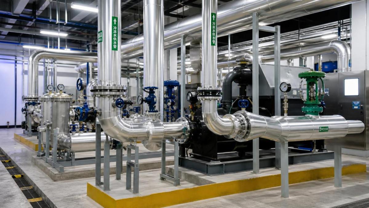
The core search intent behind chilled water piping layout is practical: determine whether a proposed arrangement will increase pumping energy or create unacceptable operational risk.
Technical evaluators are usually not looking for a generic definition of primary-secondary pumping or a simplified pipe-sizing rule. They need defensible engineering judgment.
The central question is whether the piping layout delivers required flow at every load condition with the lowest realistic differential pressure and acceptable control stability.
In high-performance facilities, the answer cannot be based solely on design-day calculations. Part-load operation often dominates annual pump electricity consumption.
A layout that appears reasonable at peak demand may waste substantial energy when production tools, cleanroom zones, or process loads operate unevenly.
Evaluators should therefore review the full hydraulic path, including chillers, air handlers, process heat exchangers, strainers, valves, meters, fittings, bypasses, and terminal branches.
Each component contributes resistance. Together, those resistances establish the pump head requirement, which strongly affects both installed capacity and annual energy use.
The most useful evaluation method connects three issues: pressure drop, operating flow range, and control response under changing loads or equipment availability.
This perspective is particularly important for semiconductor, pharmaceutical, laboratory, data-center, and precision manufacturing environments where temperature excursions carry operational consequences.
Why Piping Head Loss Drives Pump Energy
Chilled water pumps consume energy to overcome static elevation effects where relevant and, more importantly, friction losses throughout the closed-loop distribution network.
In most closed chilled water systems, static lift is not a continuous pump-energy burden because water rising in one pipe leg returns through another.
The dominant design concern is friction head. Long routes, undersized pipe, excessive fittings, restrictive valves, and poorly selected accessories all increase it.
Pump input power rises with flow and head. A useful approximation is pump power equals flow multiplied by head, divided by pump and motor efficiency.
That relationship matters because a modest head reduction can produce meaningful annual savings, particularly in systems operating continuously or with large distribution flows.
Friction loss does not increase linearly with flow. In turbulent water systems, pressure drop commonly changes approximately with the square of flow.
Consequently, a piping network with high resistance becomes especially expensive when flow increases during peak cooling loads, redundancy events, or simultaneous process demand.
Variable-speed drives can reduce energy at part load, but they cannot fully compensate for avoidable resistance embedded in the chilled water piping layout.
A pump operating against unnecessary head may still maintain flow, yet it can run away from its best efficiency point and create control instability.
Technical reviews should separate unavoidable pressure loss from losses caused by layout choices, oversized safety margins, or poorly coordinated mechanical-room and distribution design.
Pipe Routing: Shorter Is Useful, but Hydraulic Simplicity Matters More
Short pipe routes generally reduce friction, material cost, insulation area, and thermal exposure. However, the shortest drawing path is not always the best hydraulic arrangement.
A direct route with numerous offsets, tight elbows, elevation changes, and congested valve stations can impose more loss than a slightly longer but cleaner route.
Evaluators should inspect equivalent length, not only measured length. Every elbow, tee, reducer, valve, flexible connector, and specialty component adds resistance.
Long-radius elbows, appropriately sized headers, and coordinated routing can lower system pressure drop without compromising maintainability or seismic support requirements.
Mechanical rooms deserve special attention because high component density can concentrate a large share of total resistance near chillers and pump skids.
Common hidden penalties include undersized spool pieces, restrictive combination valves, excessive check-valve velocity, and unnecessary flow through standby equipment branches.
Pipe routing should also preserve accessible isolation points. Energy optimization that makes cleaning, flushing, balancing, or valve replacement difficult creates lifecycle risk.
For critical plants, routing decisions must accommodate future expansion. A low-loss initial layout can become inefficient when later branches are added without header capacity.
The best layouts use hydraulic modeling and physical coordination together. Neither a schematic diagram nor a three-dimensional model alone confirms actual operating performance.
Pipe Diameter Is an Energy and Capital Tradeoff
Selecting larger pipe reduces water velocity and friction loss, allowing lower pump head. It also increases first cost, weight, space demand, insulation expense, and installation complexity.
Selecting smaller pipe reduces initial material cost but raises pressure drop, velocity, noise potential, erosion risk, and required pump energy over the asset life.
There is no universal optimum velocity because the best choice depends on operating hours, electricity cost, water quality, pipe material, redundancy philosophy, and future demand.
Technical evaluators should request lifecycle cost comparisons rather than accepting a pipe diameter selected only from customary velocity limits or contractor preference.
A lifecycle comparison should calculate incremental pipe and installation cost against projected pump electricity, maintenance implications, and the expected service life of the facility.
The assessment should use realistic annual load profiles. A facility with continuous process cooling warrants a different optimization than an office-oriented comfort cooling plant.
Oversizing should also be disciplined. Excessively large pipe can increase capital cost without materially reducing energy if pumps already operate near efficient low-head conditions.
Conversely, high-value clean manufacturing environments may justify lower design friction rates because downtime, temperature drift, and future retrofit work are expensive.
Diameter decisions should include branch piping. Efficient mains do not compensate for terminal branches that create excessive local losses or force high differential pressure setpoints.
Loop Configuration Changes the Pumping Strategy
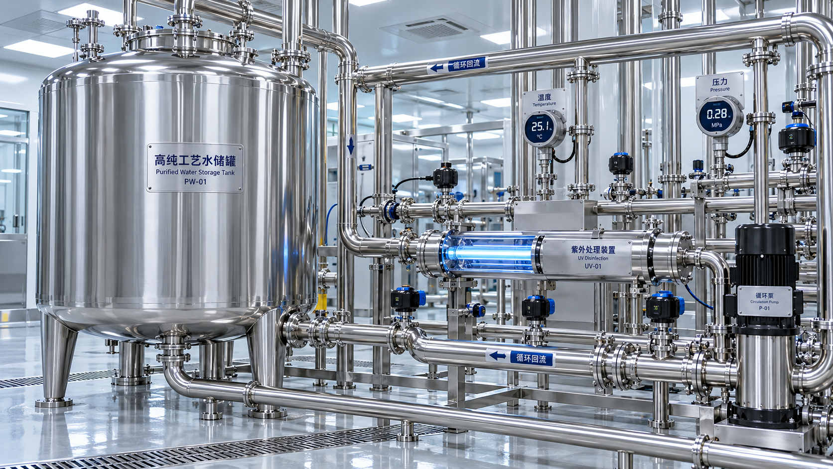
The chilled water piping layout determines how pumps interact with chillers, decouplers, distribution headers, terminal equipment, and process loads under changing conditions.
Primary-only variable-flow systems can reduce equipment count and avoid some decoupler-related losses, but they require compatible chiller flow limits and robust controls.
Primary-secondary arrangements separate chiller flow from distribution flow. They can support staged plant equipment, but poor decoupler design may cause unwanted mixing.
When flow passes through a common pipe in an unintended direction, return temperatures can be diluted, chiller efficiency can decline, and pumping behavior becomes difficult to interpret.
Variable primary flow can be highly efficient when minimum evaporator flow, chiller staging, sensor placement, and valve sequencing are carefully engineered.
Distributed pumping can reduce long distribution pressure requirements in large campuses, but it introduces more control points and requires clear responsibility boundaries.
For high-availability facilities, ring mains and dual-ended distribution improve resilience. Their energy impact depends on balancing, valve positions, and normal operating configuration.
A redundant path that remains fully open during normal operation may unintentionally encourage excess flow and lower resistance, making balancing behavior unpredictable rather than efficient.
Evaluators should ask for operating narratives covering normal load, low load, peak load, one-pump failure, one-chiller isolation, expansion phase, and emergency operation.
Control-Valve Authority Can Raise or Lower Pumping Demand
Control valves regulate flow through coils, process heat exchangers, and terminal units. Their sizing directly affects stable temperature control and system differential pressure requirements.
An oversized control valve may have low authority. Small changes in valve position can produce large flow changes, causing hunting and poor temperature stability.
Operators often respond to unstable terminals by raising pump differential pressure. That response may restore flow temporarily while increasing energy use across the entire system.
Undersized valves create the opposite problem: they restrict design flow and can force higher pump head, even though nearby branches receive excessive pressure.
Proper valve authority requires comparing valve pressure drop with the available pressure drop across the controlled branch at relevant operating conditions.
Pressure-independent control valves can simplify flow limitation in variable-flow networks, especially where branch pressure changes are substantial across different operating states.
They are not automatically the lowest-loss solution. Their pressure requirements must be included honestly in the pump head calculation and control sequence evaluation.
For precision applications, valve selection should consider close-off pressure, leakage class, actuator resolution, fail position, water cleanliness, and maintainability alongside pressure loss.
The design objective is not merely to make every valve work. It is to make the system controllable at the lowest sustainable differential pressure.
Hydraulic Balancing Determines Whether Design Intent Survives Commissioning
Even a sound chilled water piping layout can perform poorly when flow distribution is not balanced. Water follows the path of least resistance.
Branches near pumps or headers may receive too much flow, while remote coils or process loads experience insufficient flow during critical demand periods.
Traditional manual balancing valves can establish design flow, but their fixed resistance may become an ongoing pumping penalty when load conditions vary considerably.
Automatic flow-limiting devices, differential pressure controllers, and intelligent valves can improve stability, although each device must be evaluated for pressure loss and control compatibility.
Balancing should not be treated as a final construction task only. It should influence pipe sizing, branch topology, valve placement, and sensor strategy during design.
Commissioning data should verify actual pump curves, operating differential pressure, valve positions, coil flow, return temperature, and pressure at hydraulically remote points.
Remote-point measurement is essential because pump discharge pressure alone does not show whether the critical branch receives adequate available pressure at part load.
A strong sequence resets pump differential pressure downward until one or more critical valves approach their required operating position, then maintains an appropriate margin.
This approach reduces unnecessary pressure while protecting terminal control. It requires trustworthy sensors, validated valve signals, and a carefully selected critical-zone logic.
Low Delta-T Symptoms Often Point Back to Distribution Design
Low chilled water temperature differential is frequently discussed as a chiller-plant problem, yet piping layout and flow control often contribute directly to the condition.
When coils receive more water than needed, return water temperature rises less than expected. Plant flow increases while useful cooling per unit flow declines.
This can require additional pumps and chillers to operate, increasing both pumping energy and cooling-plant energy during periods that should be manageable.
Overflow through three-way valves, bypass lines, decouplers, improperly selected coils, and uncontrolled minimum flows can all reduce effective system delta-T.
Technical evaluators should identify every potential short-circuit path between supply and return headers. These paths may be necessary in limited conditions but harmful when uncontrolled.
Bypasses should have a clear operational purpose, defined control criteria, documented minimum-flow requirements, and measurement points to prove their actual use.
In precision facilities, process equipment may have legitimate minimum-flow constraints. The design should isolate these needs rather than imposing high flow on the entire network.
Maintaining design delta-T is not simply an efficiency target. It protects plant capacity, supports predictable staging, and reduces pressure-related operational interventions.
How to Review a Chilled Water Piping Layout Before Approval
A disciplined review begins with a hydraulic profile from the most hydraulically remote load back to the pump suction connection through every active component.
Request pressure-drop schedules at design flow and representative part-load flows. A single total-head value does not reveal where resistance is concentrated.
Check whether the stated critical path remains critical after equipment staging, isolation-valve changes, future expansion, or alternate plant operating modes.
Review pump selection against the system curve, including expected operating points, minimum stable flow, efficiency islands, net positive suction head, and parallel-pump behavior.
Ask whether variable-speed pumps can reduce speed without violating chiller minimum flow, terminal valve authority, process requirements, or differential pressure control limits.
Verify that meters and sensors are placed where they support diagnosis. Flow, pressure, and temperature measurements should distinguish plant problems from distribution problems.
Evaluate redundancy hydraulically, not only schematically. Standby branches, duty-standby pumps, and alternate routes should be tested for their normal and failure-mode losses.
Finally, require a commissioning plan that includes functional testing of pump reset logic, valve behavior, balancing, chiller staging, and low-load temperature control.
Conclusion: Treat Layout as a Long-Term Energy Decision
A chilled water piping layout affects pump energy use because every routing, sizing, valve, and configuration choice changes the resistance pumps must overcome.
For technical evaluators, the strongest designs do not chase the lowest first cost or the lowest theoretical pressure drop in isolation.
They balance lifecycle energy, temperature control, maintainability, resilience, commissioning practicality, and compliance requirements across the complete chilled water distribution system.
The key decision criterion is straightforward: minimize avoidable pressure loss while preserving reliable flow and stable control at every critical load condition.
When evaluated through hydraulic modeling, lifecycle cost analysis, and realistic operating scenarios, piping design becomes a measurable contributor to facility efficiency and operational confidence.