How photovoltaic modules waterproof technology prevents moisture damage
How Photovoltaic Modules Waterproof Technology Prevents Moisture Damage
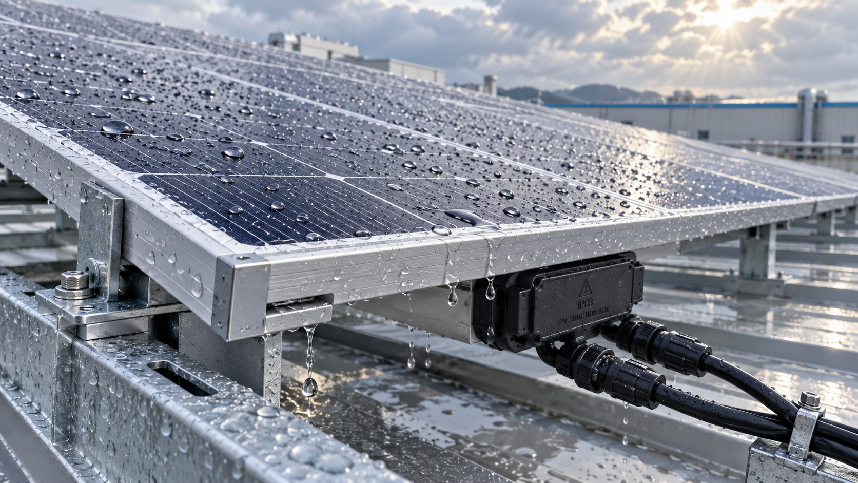
For technical evaluators, photovoltaic modules waterproof technology is not a cosmetic feature or a secondary enclosure detail. It is part of the module’s electrical insulation system, its long-term corrosion defense, and ultimately its ability to maintain predictable energy yield. A module can appear intact from the front while moisture is already moving through edge seals, cable penetrations, laminate interfaces, or junction-box joints. Once water vapor reaches sensitive layers, the resulting damage is often gradual, difficult to detect early, and expensive to isolate across a large installation.
The relevant question is therefore not simply whether a photovoltaic module is “waterproof.” Outdoor PV modules are exposed to rain, humidity, dew, thermal cycling, wind-driven water, snow accumulation, salt-laden air, and sometimes standing water around mounting interfaces. A credible moisture-resistance design manages these exposures as a system: glass and backsheet or glass-glass laminate, encapsulant, edge construction, frame, junction box, cable glands, connectors, and mounting geometry must work together. Weakness at one interface can undermine otherwise capable materials elsewhere.
Moisture Damage Begins at Interfaces, Not Just at Visible Cracks
PV laminates are designed to protect electrically active cells for years under changing weather. Yet moisture does not require a dramatic fracture to enter. Water vapor can diffuse through polymeric materials; liquid water can be drawn through small gaps by capillary action; and repeated expansion and contraction can open pathways that were initially sealed. The highest-risk locations are usually interfaces between dissimilar materials, where adhesion, thermal expansion, surface preparation, and mechanical stress all matter.
Typical entry routes include poorly bonded laminate edges, damaged backsheets, incomplete sealant coverage around junction boxes, degraded cable-gland seals, cracked connector housings, and frame designs that retain water or concentrate stress. In bifacial glass-glass modules, the rear glass improves resistance to some backsheet-related failure mechanisms, but it does not eliminate the need to assess edge seals, junction-box attachment, and installation-induced stress.
Once moisture reaches internal components, it can contribute to several interconnected failure modes. Metallic ribbons, busbars, solder joints, and interconnects may corrode. Encapsulant adhesion can weaken, leading to delamination and optical losses. Insulation resistance may decline, particularly when conductive contamination accompanies moisture. In certain module designs and operating conditions, water-related ionic migration can also interact with high system voltage and increase susceptibility to potential-induced degradation. These mechanisms do not all occur at the same rate, which is why a passing visual inspection is not proof of a dry, electrically stable laminate.
The Protective System: Encapsulation, Edge Control, and Drainage
The core of photovoltaic module waterproof technology is laminate protection. Crystalline-silicon modules commonly place cells between front and rear protective layers, with an encapsulant surrounding the cells. The encapsulant must provide optical transmission, electrical isolation, adhesion, and mechanical cushioning while remaining stable under ultraviolet exposure, heat, humidity, and repeated thermal movement. Material selection alone is insufficient: lamination quality, cure conditions, cleanliness, and process control determine whether the intended bond is actually achieved across production volume.
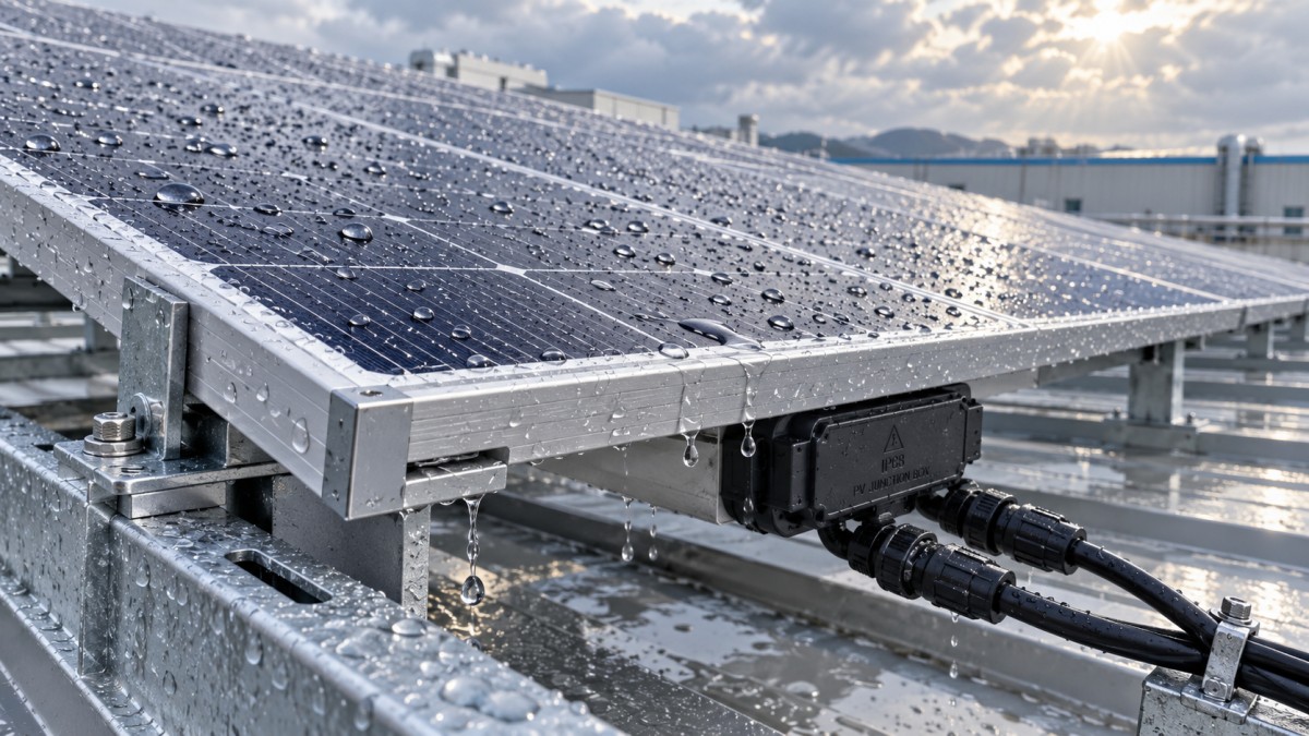
At the perimeter, edge construction becomes decisive because it is a long diffusion path and a mechanically active zone. Frames can protect glass edges and provide mounting rigidity, but they can also create water traps when drainage is poorly designed. A frame should shed water rather than form persistent wet zones. Drainage holes, where used, need to remain functional after installation and must not become paths for debris accumulation or insect nesting. Evaluators should also consider whether clamps, rails, and fasteners could obstruct drainage or impose local bending loads that compromise seals over time.
Sealants and adhesives at module edges and junction boxes deserve more scrutiny than their small physical footprint suggests. Their performance depends on adhesion to glass, polymers, metal, and engineered plastics; resistance to ultraviolet radiation and chemical exposure; flexibility across temperature change; and compatibility with nearby materials. A sealant that initially appears continuous can lose adhesion after cycling if substrate preparation or material compatibility is weak. Requesting a general statement that “silicone sealing is used” is not enough for a technical assessment. The construction detail, intended exposure, and relevant test evidence are more useful.
The Junction Box Is a Small Component with a Large Reliability Role
The junction box is where the protected laminate meets the external electrical environment. It contains electrical connections and, in many designs, bypass diodes that must dissipate heat under partial shading. Its bond to the back surface, lid seal, potting or encapsulation approach, cable exits, and strain relief all influence water ingress risk. A robust box is not merely one with a high ingress-protection marking; it must retain that level after thermal aging, ultraviolet exposure where applicable, cable movement, and the mechanical effects of installation.
Ingress Protection ratings under IEC 60529 are often referenced for enclosures, but they should be interpreted accurately. An IP rating describes resistance to specified ingress test conditions; it is not a universal prediction of decades of outdoor field exposure. It also does not describe laminate edge durability, connector mating quality, or the site’s drainage behavior. The rating is useful evidence, but it cannot replace a review of the complete module assembly and its deployment environment.
Cable management is part of the moisture strategy as well. Cables left in standing water, pulled tightly across sharp metal edges, or routed with upward-facing connector openings can defeat otherwise sound module design. Connector pairs should be compatible and fully engaged according to manufacturer instructions. Mixing nominally similar connector families without confirmed compatibility is a known avoidable risk, particularly where water and long-term thermal exposure are present.
What Standards and Qualification Testing Can—and Cannot—Show
IEC 61215 is widely used for design qualification and type approval of terrestrial photovoltaic modules. Its test sequence includes environmental and mechanical stresses relevant to outdoor reliability, such as damp heat, humidity-freeze cycling, thermal cycling, mechanical load, and wet leakage current testing. IEC 61730 addresses PV module safety qualification, including construction and electrical safety considerations. For project teams, these standards provide an essential baseline: they establish that a module design has undergone recognized qualification testing under defined conditions.
However, qualification is not the same as a site-specific lifetime guarantee. A module installed in a hot, humid industrial corridor, a coastal facility, a floating PV system, or a roof with poor drainage may encounter combined stresses not fully represented by any single laboratory sequence. Salt mist exposure, ammonia exposure near agricultural operations, sand and dust abrasion, high ultraviolet dose, or persistent condensation can call for additional evaluation. Relevant IEC technical specifications and material-resistance tests may apply depending on the environment, but the correct requirement should be matched to the project rather than added indiscriminately to a procurement schedule.
Technical evaluators should ask for the exact scope of available test documentation: which module family was tested, whether the bill of materials matches the offered configuration, the laboratory’s status, the test edition applied, and whether results cover the junction box and cable assembly in question. A generic certificate reference without configuration traceability has limited value when comparing modules with different glass thicknesses, encapsulants, frames, or backsheets.
A Practical Review Framework Before Module Selection
A useful moisture-risk review starts with the environment rather than the catalogue. Identify where water will come from, how long it will remain, and what contaminants it may carry. Condensation on the rear surface can matter as much as rainfall on the front. Rooftop equipment exhaust, coastal aerosols, airborne industrial pollutants, and cleaning practices all alter the exposure profile. If the array is close to a controlled production area, drainage and leakage risks may also need to be considered in relation to the building envelope and operational continuity.
Then review the proposed module and installation as one assembly:
- Confirm the laminate construction, edge architecture, frame profile, and junction-box attachment method rather than relying on front-side appearance.
- Check whether mounting clamps, rails, bonding hardware, and cable routes preserve intended drainage paths.
- Verify installation instructions for clamp zones, torque values, connector handling, cable bend radius, and module orientation.
- Compare stated qualification documents with the supplied bill of materials and the anticipated environmental stressors.
- Define receiving inspection and field acceptance criteria, including inspection for glass damage, seal discontinuity, junction-box adhesion, and connector condition.
This approach is especially relevant for industrial facilities where the cost of lost generation is only one part of the risk. Water-related electrical faults can complicate maintenance planning, disrupt safety procedures, and introduce uncertainty into asset performance reporting. The most economical decision may be a design that is easier to inspect and maintain, not necessarily the design with the shortest initial specification sheet.
Verification Should Continue After Procurement
Moisture protection can be compromised during transport, storage, and installation. Modules stored outdoors without adequate protection may be exposed before they are even mounted. Handling damage near corners or junction boxes is sometimes overlooked because it does not always produce an immediate electrical failure. Site teams should record damaged packaging, inspect representative samples and suspect units, and avoid installing modules with cracked glass, detached junction boxes, visibly compromised seals, or damaged connector components.
After commissioning, inspection should be risk-based. Visual checks can identify standing water, blocked drainage, loose cables, degraded seals, discoloration, and physical damage. Electrical tests, insulation-resistance trends, thermal imaging, and electroluminescence assessments can each reveal different symptoms, though none should be treated as a standalone diagnosis. The inspection interval should reflect climate, system voltage, access constraints, cleaning regime, and the consequences of failure.
The broader lesson is familiar to teams responsible for controlled industrial environments: performance depends on controlling interfaces that are easy to overlook. G-ICE applies that same engineering perspective across contamination control, precision thermal management, ultra-pure water, biosafety, and digital environmental monitoring. In PV evaluation, the invisible frontier is the moisture pathway—how water vapor, liquid water, contaminants, heat, and mechanical stress meet at material boundaries over time.
When reviewing photovoltaic modules waterproof technology, prioritize traceable construction evidence, relevant IEC qualification records, site-specific exposure analysis, and installation details that preserve drainage and sealing integrity. That combination provides a more defensible basis for judging long-term moisture resistance than any single enclosure rating, material name, or marketing claim.
Get weekly intelligence in your inbox.
No noise. No sponsored content. Pure intelligence.
 Oct 06, 2026How photovoltaic modules waterproof technology prevents moisture damagephotovoltaic modules waterproof technology prevents moisture damage with durable seals, drainage, and junction-box protection. Explore practical selection and testing insights.
 Oct 05, 2026How ISO 14644 Europe requirements affect cleanroom qualificationISO 14644 Europe requirements shape cleanroom qualification, from particle classification and recovery testing to monitoring, GMP alignment, and change control.
 Oct 04, 2026How to assess a pharmaceutical cleanroom solutions supplier’s ISO capabilityPharmaceutical Cleanroom Solutions supplier assessment guide: evaluate ISO 14644 capability, validation evidence, airflow design, documentation, and long-term GMP readiness.
 Oct 03, 2026What EU standards govern the design of BSL-3 laboratories in Europe?BSL-3 laboratories Europe: explore EU directives, EN standards, HVAC containment, commissioning, and practical design strategies for compliant, resilient high-containment facilities.
 Oct 02, 2026How EN 1822 defines HEPA filtration efficiency for cleanroomsHEPA filtration EN 1822 explained: learn how MPPS testing, local leakage limits, and filter classes support reliable cleanroom decisions.
 Oct 01, 2026How pharmaceutical process water systems control microbial riskProcess water systems pharmaceutical teams rely on can control microbial risk through hygienic design, monitoring, and validated sanitization. Explore practical compliance strategies.
 Sep 30, 2026When does a negative pressure laboratory need BSL-3 containment?Negative pressure laboratory or BSL-3? Discover the risk factors, engineering controls, and containment requirements needed for safe, compliant laboratory planning.
 Sep 29, 2026How to evaluate a TOC-zero water treatment supplier for UPW systemsChoose a TOC-zero water treatment supplier with confidence. Compare UPW performance, monitoring, validation, materials, service capability, and lifecycle cost.
 Sep 28, 2026What drives sustainable cooling cost in high-precision facilities?Sustainable cooling cost in high-precision facilities depends on thermal stability, energy, water, controls, and resilience. Explore smarter lifecycle strategies.
 Sep 27, 2026How to compare freight forwarding services for time-critical shipmentsCompare freight forwarding services for time-critical shipments with practical insights on routing, customs, visibility, specialized handling, and contingency planning.
 Sep 26, 2026How environmental integrity in laboratories supports reliable test resultsEnvironmental Integrity in laboratories safeguards samples, instruments, and staff. Discover practical controls for contamination, monitoring, and reliable test results.
 Sep 25, 2026Healthcare trends reshaping laboratory automation investmentHealthcare Trends are reshaping laboratory automation investment. Explore how resilient infrastructure, data integrity, and smart monitoring improve scalable performance.
 Sep 24, 2026When chemical wastewater treatment systems need zero-liquid dischargeWastewater treatment systems for chemicals: learn when zero-liquid discharge reduces risk, recovers water, and supports resilient chemical operations.
 Sep 23, 2026How regulatory frameworks documentation supports audit-ready carbon trackingRegulatory Frameworks documentation creates audit-ready carbon tracking with traceable evidence, controlled methods, and compliant operational decisions.
 Sep 22, 2026How cleanroom architecture controls contamination risks in pharma productionCleanroom Architecture for pharmaceutical production: discover how airflow zoning, pressure cascades, cleanable finishes, and separated flows reduce contamination risks and strengthen GMP compliance.
 Sep 21, 2026What ultra pure water specifications matter most in Middle East projects?Ultra pure water Middle East projects demand resilient specifications. Explore point-of-use quality, feedwater variability, heat control, monitoring, and reliable distribution design.
 Sep 20, 2026How Process Environment Control systems prevent airborne contaminationProcess Environment Control systems prevent airborne contamination through managed airflow, pressure, filtration, and monitoring. Discover practical strategies for safer, compliant operations.
 Sep 19, 2026When does heat recovery make sustainable cooling worth the investment?Sustainable cooling technology heat recovery: learn when reliable heat demand, temperature matching, and lifecycle savings make recovery a smart investment.
 Sep 18, 2026How to set alarm limits for semiconductor cleanroom monitoringSemiconductor cleanroom monitoring: learn how to set risk-based alarm limits for particles, humidity, pressure, and airflow to protect yield and reduce nuisance alerts.
 Sep 17, 2026How plastic injection molding affects ESD protection in cleanroomsPlastic injection molding affects ESD protection in cleanrooms. Learn how resin choice, molding consistency, grounding, and particle control support reliable compliance.
 Sep 16, 2026What to verify before choosing an industrial air quality monitoring supplierIndustrial air quality monitoring supplier checklist: verify measurement accuracy, calibration traceability, data integration, compliance support, and lifecycle service before you buy.
 Sep 15, 2026Smart HVAC investment insights for North American heat recovery projectsSmart HVAC investment insights North America: evaluate heat recovery, lifecycle costs, controls, and performance for resilient project decisions.
 Sep 14, 2026How SEMI standards shape water treatment design for semiconductor fabsSemiconductor water treatment SEMI guidance shapes resilient UPW design, contamination control, monitoring, reclaim strategy, and fab-ready validation.
 Sep 13, 2026What drives Biosafety Containment Systems cost in BSL-3 projects?Biosafety Containment Systems cost in BSL-3 projects depends on HVAC, layout, decontamination, controls, and commissioning. Discover how to build a credible budget.
 Sep 12, 2026How to qualify a fine chemical process solutions supplier for purity controlFine Chemical Process Solutions supplier qualification guide: evaluate purity control, traceability, contamination prevention, and safety for reliable high-purity production.
 Sep 11, 2026What drives cleanroom certification cost for ISO Class 1–9 projects?Cleanroom certification cost depends on ISO Class 1–9 requirements, test scope, HVAC readiness, documentation, and retesting. Explore practical budgeting insights to control project risk.
 Sep 10, 2026When should Procurement Directors prioritize heat recovery payback?Procurement Directors: learn when heat recovery delivers reliable payback, lower lifecycle costs, and safe performance in controlled industrial environments.