When do heat pipe heat exchangers suit pharmaceutical cleanrooms?
When Do Heat Pipe Heat Exchangers Suit Pharmaceutical Cleanrooms?
Heat Pipe Heat Exchangers for pharmaceutical plants make the most sense when a cleanroom needs energy recovery but cannot accept direct contact, carryover, or a shared air path between exhaust and incoming outdoor air. That sounds straightforward, yet the selection is rarely just an efficiency question. In pharmaceutical HVAC, the heat exchanger sits inside a larger control strategy involving pressure cascades, air-change requirements, humidity limits, filtration stages, cleanability, maintenance access, and qualification evidence.
A heat pipe can be a very practical answer for an aseptic filling support area, a sterile manufacturing suite, or a production zone exhausting conditioned air at a temperature materially different from the outdoor-air stream. It can also be the wrong choice when dehumidification capacity, space constraints, frost risk, or exhaust contaminants demand a different recovery arrangement. The useful question is not “Is a heat pipe efficient?” It is whether it supports the environmental control philosophy of the room without creating a validation or maintenance burden that outweighs the recovered energy.
Why pharmaceutical cleanrooms look at heat pipes in the first place
A conventional heat pipe heat exchanger consists of sealed tubes containing a working fluid. One section of the tube absorbs heat from the warmer air stream; the other releases that heat to the cooler stream. In cooling seasons, warm exhaust air can pre-cool incoming outdoor air before it reaches the cooling coil. In heating seasons, the same arrangement can preheat outdoor air using energy from exhaust air.
The attraction is that the supply and exhaust airstreams remain physically separated. There is no rotating wheel transferring energy from one stream to another, no glycol loop to circulate, and generally no pump package associated with the recovery device itself. In facilities where exhaust may contain active pharmaceutical ingredient dust, cleaning-agent vapours, bioaerosol concerns, or material generated in containment operations, that separation deserves serious attention.
This does not mean a heat pipe automatically eliminates contamination risk. It only removes one important transfer mechanism: direct air exchange through the recovery medium. The AHU casing, partition integrity, drain arrangements, access doors, gasket quality, pressure differentials, and duct leakage still matter. A poorly detailed installation can undermine the theoretical advantage of an otherwise suitable exchanger.
For technical teams assessing high-performance environments, this is where the broader G-ICE perspective is useful: thermal recovery cannot be evaluated in isolation from contamination control, containment, monitoring, and the operating logic of the whole air system. A heat pipe is an HVAC component, but its acceptability is decided at the interface between engineering performance and the facility’s quality framework.
The best-fit operating conditions
Heat pipes are generally strongest in dedicated outdoor-air or supply-and-exhaust AHU arrangements where the two air streams can pass adjacent to one another and where there is a reliable temperature difference for much of the operating year. Pharmaceutical plants with substantial outside-air volumes are often candidates because the cost of conditioning outdoor air can be significant, especially when rooms operate continuously or maintain demanding temperature and humidity conditions.
They are particularly worth evaluating in the following situations:
- Supply and exhaust fans serve closely paired air paths in the same AHU or in an integrated recovery section.
- The project requires sensible energy recovery while preserving strict separation between incoming and discharged air.
- The exhaust air is warm or cool enough to create a meaningful driving temperature difference, rather than merely being near outdoor conditions.
- The facility values a passive device with no compressor, circulation pump, or rotating energy-transfer element.
- Maintenance teams can access both coil faces for inspection and cleaning without entering a classified area in an uncontrolled way.
A common pharmaceutical example is an air-handling unit serving a production area that exhausts conditioned room air while bringing in a substantial volume of outdoor air for pressurisation and air-change requirements. If the room exhaust is cooler than hot outdoor air, the heat pipe can reduce the sensible load reaching the cooling coil. In a colder climate, it may reclaim heat from exhaust air to temper outdoor air before heating. The exact seasonal benefit must be modelled from local weather conditions, airflow rates, coil geometry, and unit operating schedules; it should not be assumed from a generic recovery-efficiency claim.
The humidity question: where many selections become too optimistic
Most heat pipe designs are primarily sensible recovery devices. They move heat, not moisture, between the two air streams. This can be exactly what a pharmaceutical cleanroom wants when cross-stream moisture transfer is undesirable. But it also means the device should not be credited with solving a demanding latent-load problem.
That distinction matters in oral solid dosage areas, sterile suites, packaging rooms with moisture-sensitive materials, and facilities located in humid climates. If outdoor-air dehumidification is the central design challenge, a heat pipe may reduce the temperature of incoming air before it reaches a cooling coil, but the cooling and reheat strategy still has to deliver the required dew point. The coil leaving condition, reheat approach, condensate management, control sequence, and room moisture gains need to be assessed together.
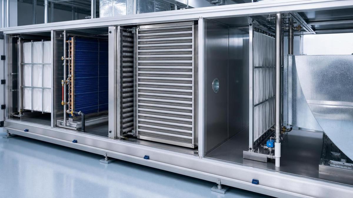
A heat pipe can also be arranged as a heat-pipe dehumidification system in certain AHU configurations: one section pre-cools incoming air upstream of a cooling coil, while another reheats the air downstream. This can reduce the need for separate reheat in some conditions. Even then, it does not create latent capacity by itself. It changes how the cooling coil and reheat process are used. Teams should request performance data at actual entering-air conditions, rather than relying on a nominal temperature-effectiveness figure.
Airflow separation is valuable, but it must be engineered—not assumed
Pharmaceutical operations often separate exhaust categories for good reasons. General room return air, solvent-related exhaust, powder-handling exhaust, biosafety exhaust, and high-containment discharge may have very different risk profiles. A heat pipe should not be selected simply because it appears “non-contact.” The first question is what is actually in the exhaust stream and where that stream is allowed to travel.
For hazardous or highly potent compounds, the project’s containment assessment may dictate dedicated exhaust, filtration, safe-change arrangements, discharge location, and pressure monitoring independent of any energy-recovery objective. A heat pipe may remain feasible if the exchanger is built into an appropriately segregated, pressure-managed AHU section, but it must not compromise the exhaust system’s primary safety function.
Physical separation also deserves inspection-level detail. Ask how the supply and exhaust plenums are divided, how seals are tested, where condensate can form, and whether any bypass path exists around the coil frame. Consider the pressure relationship across the partition. If leakage does occur, it is preferable that the resulting direction supports the clean-air side rather than drawing exhaust contaminants toward supply air. The answer depends on the layout and fan arrangement, so it has to be reviewed on the actual unit drawing.
Cleanability and qualification are not afterthoughts
In a standard commercial building, a recovery coil may receive limited attention until pressure drop rises or performance declines. That operating habit does not translate well to pharmaceutical environments. Coil surfaces can collect airborne particles, and wet sections can create avoidable hygiene concerns if condensate is not drained and accessible areas are not cleaned properly.
The practical review should cover fin spacing, material compatibility with the intended cleaning method, drain-pan design where condensation is possible, access-door placement, lighting and inspection visibility, and the ability to remove or service components without disrupting surrounding controlled spaces. If technicians need to enter an interstitial zone or open a contaminated exhaust section, maintenance procedures should reflect that reality. A theoretically low-maintenance device is still a maintenance item in a GMP environment.
Qualification teams will usually need a clear design rationale: why the recovery arrangement does not compromise the required air quality, pressure regime, or environmental controls. The exact documentation burden varies by project and jurisdiction, but the engineering package should make it possible to trace the logic from user requirements through design specification, installation checks, functional testing, and ongoing monitoring. Standards such as ISO 14644 can inform cleanroom classification and testing considerations, while pharmaceutical GMP expectations and local requirements determine the wider compliance context. Neither should be treated as a shortcut to approving a particular heat-exchanger type.
Where a heat pipe is less convincing
There are several situations where the heat pipe may be technically possible but commercially or operationally weak. One is a plant with supply and exhaust systems located far apart. Heat pipes need close thermal coupling between the relevant air streams, so a runaround coil loop may offer more layout flexibility despite requiring pumps, fluid quality management, and additional controls.
Another is an application with severe winter conditions. Frost can limit recovery performance when exhaust-side surfaces fall below freezing conditions. A suitable design may need bypass control, face-and-bypass sections, staged operation, or another frost-management method. The control sequence should be tested against low-ambient scenarios, not left as a generic note in the specification.
High pressure drop is another frequent blind spot. Cleanrooms already carry pressure penalties from high-efficiency filtration, terminal devices, ductwork, and sometimes multiple treatment stages. Adding a recovery coil affects fan selection and may increase operating energy. A heat pipe should therefore be evaluated using net system impact: sensible recovery, added fan power, coil fouling allowance, space implications, and maintenance access. Looking only at thermal effectiveness gives an incomplete answer.
Finally, facilities needing significant moisture transfer or total-energy recovery should compare alternatives carefully. A rotary energy-recovery wheel can provide stronger total-energy exchange in some applications, but it introduces concerns over carryover, purge arrangements, cleaning, and acceptability for the exhaust category. In pharmaceutical cleanrooms, the “highest recovery” option is not automatically the lowest-risk option.
Questions to settle before specifying the unit
Before approving Heat Pipe Heat Exchangers for pharmaceutical plants, an evaluator should ask for more than a catalogue schedule. Confirm the supply and exhaust design airflows, seasonal entering conditions, target leaving conditions, permitted pressure drop, and the full operating range rather than a single design point. Review whether the coil is fixed, tiltable, or uses another control method, because part-load operation matters in real facilities.
Also establish the exhaust classification. Is it ordinary conditioned room exhaust, potentially dusty process exhaust, chemically aggressive air, or air tied to biosafety containment? The answer influences materials, filtration strategy, access provisions, and whether energy recovery is appropriate at all. A separate review is needed for corrosive compounds and cleaning chemicals, since tube, fin, casing, seal, and drain materials must withstand the expected environment.
Then review the control narrative with the cleanroom sequence of operations. The recovery device should not interfere with room pressure control, temperature stability, humidity response, smoke-control obligations where applicable, or the ability to isolate a system during an abnormal event. Integration with smart environmental monitoring can be useful, but the measured variables must support a defined operational decision rather than merely adding another dashboard point.
A sound decision is usually a balanced one
Heat pipe heat exchangers are a strong option for pharmaceutical cleanrooms when sensible energy recovery is needed, supply and exhaust streams can be closely paired, and physical separation between those streams is a governing requirement. Their passive operation and lack of direct air transfer can simplify the risk discussion compared with some alternatives. But they do not remove the need for careful humidity design, leakage control, frost planning, coil access, and qualification documentation.
The most defensible specification is one that starts with the cleanroom’s contamination and control requirements, then tests the heat pipe against real airflow, climate, exhaust, maintenance, and validation conditions. If those conditions line up, the device can be a disciplined engineering choice—not just an energy-saving accessory added late in the AHU design.
Get weekly intelligence in your inbox.
No noise. No sponsored content. Pure intelligence.
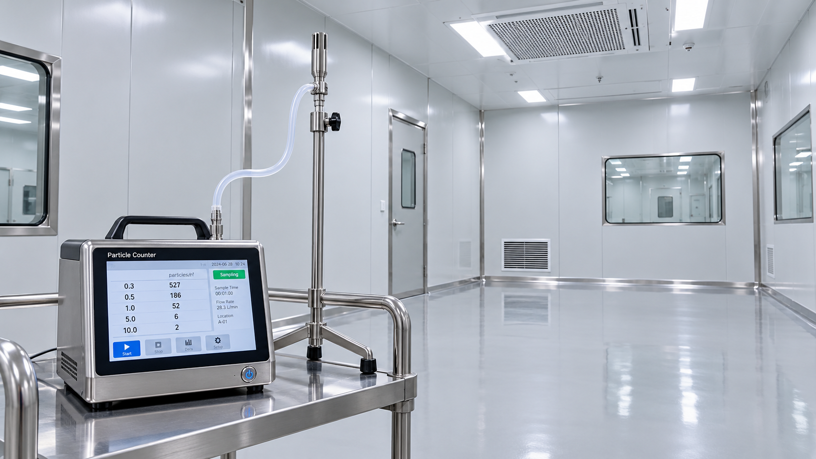
 Oct 21, 2026How often is cleanroom certification required under ISO 14644-2?Cleanroom Certification is generally recommended annually under ISO 14644-2. Learn when risk-based extensions apply and which changes trigger earlier testing to plan with confidence.
 Oct 21, 2026FASEB Comments on NIH Draft Policy for Research Involving BiohazardsFASEB comments on NIH’s draft biohazard research policy call for risk-based biosafety oversight. Explore potential implications for laboratories, suppliers, and compliance teams.
 Oct 20, 2026How to disinfect ultrasound machines without damaging surfacesLearn how to disinfect ultrasoundmachines without surface damage. Explore compatible products, wet contact times, and probe care to protect patients and equipment.
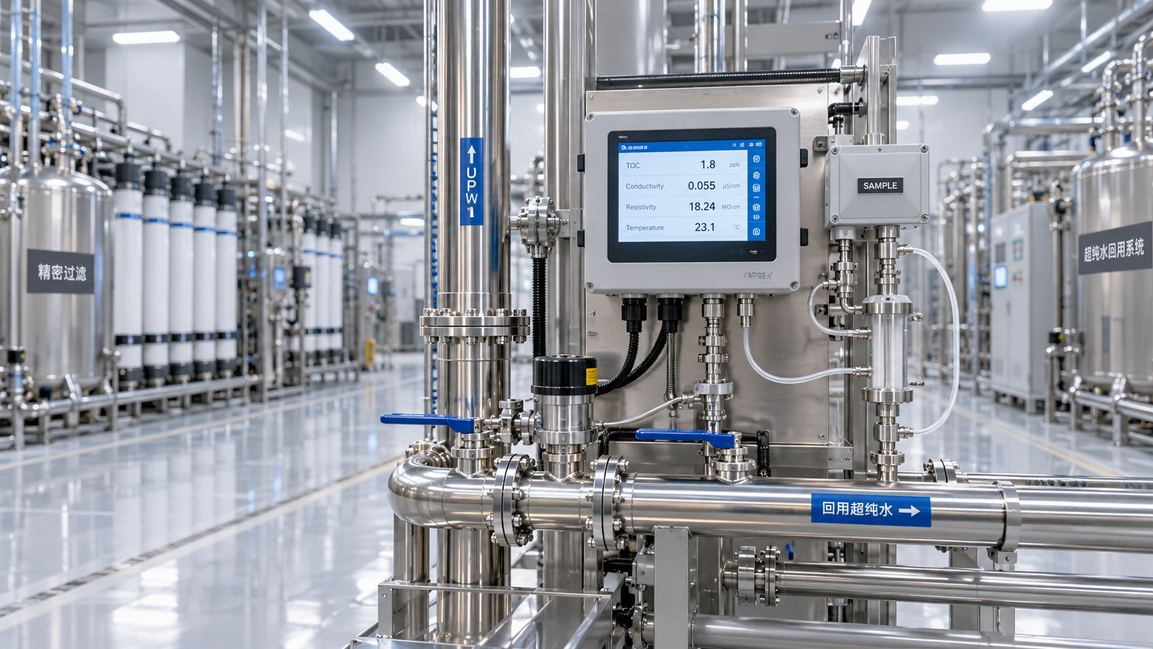
 Oct 20, 2026Ultrapure Water in Semiconductor Manufacturing: Reuse and Quality Control InsightsExplore ultrapure water reuse in semiconductor manufacturing, key UPW quality benchmarks and analytical insights to help evaluate suppliers and protect process purity.
 Oct 19, 2026How cooling affects warpage in injection-molded consumer electronics housingsOptimize plastic injection molding for consumer electronics with cooling strategies to reduce housing warpage and improve assembly fit. Discover practical checks for stable, efficient production.
 Oct 18, 2026Can air leaks prevent a dehumidifier from holding its target dew point?Why can't our dehumidifier maintain the target dew point? Discover how air leaks increase moisture loads, spot hidden faults, and find practical fixes to restore reliable dew-point control.
 Oct 17, 2026How semiconductor process water treatment removes trace organicsSee how semiconductor process water treatment removes trace organics with RO, UV oxidation, and polishing. Learn how TOC monitoring helps verify purity and pinpoint contamination.
 Oct 16, 2026How to choose ultra pure water piping materials to limit leachingChoose ultra pure water piping with confidence. Compare PVDF, PFA, and stainless steel, assess leaching risks, and learn how to qualify your system for reliable purity.
 Oct 15, 2026How to size a skid-mounted deionized water system for peak demandCompare deionized water systems skid configurations for peak demand. Learn how to balance production, storage, and pump capacity to prevent shortages and avoid costly oversizing.
 Oct 14, 2026When is collaborative laboratory robotics suitable for sample sorting?Explore when collaborative laboratory robotics suits sample sorting. Discover key checks for safety, traceability, container compatibility, and throughput before choosing your solution.
 Oct 13, 2026How sandwich panel joints affect airtightness in cleanroom systemsCleanroom Systems sandwich panels need reliable joints for airtightness. Discover how gaskets, sealants, and testing help reduce leakage and protect cleanroom pressure control.
 Oct 12, 2026How to verify USP compliance for ultra pure water systemsUltra Pure Water Systems USP compliance: learn how to verify water quality, sampling, sanitization, trends, and validation controls at every point of use.
 Oct 11, 2026How tight temperature control prevents cleanroom process driftCleanroom process temperature control systems prevent costly drift by stabilizing critical conditions, improving repeatability, and protecting sensitive production workflows.
 Oct 10, 2026When does organic contaminant removal require TOC treatment?Organic contaminant removal requires TOC treatment when dissolved organics threaten product quality, equipment reliability, or process control. Learn how to assess risks and choose the right solution.
 Oct 08, 2026What affects lead times for sheet metal bending services in Canada?Sheet metal bending services Canada: discover how material supply, tooling, tolerances, finishing, documentation, and freight affect lead times for reliable project delivery.
 Oct 07, 2026How HVAC design for semiconductor fabs prevents airborne contaminationHVAC design for semiconductor fabs prevents airborne contamination through advanced filtration, pressure cascades, airflow control, and real-time monitoring. Explore key strategies for cleaner, more reliable wafer production.
 Oct 06, 2026How photovoltaic modules waterproof technology prevents moisture damagephotovoltaic modules waterproof technology prevents moisture damage with durable seals, drainage, and junction-box protection. Explore practical selection and testing insights.
 Oct 05, 2026How ISO 14644 Europe requirements affect cleanroom qualificationISO 14644 Europe requirements shape cleanroom qualification, from particle classification and recovery testing to monitoring, GMP alignment, and change control.
 Oct 04, 2026How to assess a pharmaceutical cleanroom solutions supplier’s ISO capabilityPharmaceutical Cleanroom Solutions supplier assessment guide: evaluate ISO 14644 capability, validation evidence, airflow design, documentation, and long-term GMP readiness.
 Oct 03, 2026What EU standards govern the design of BSL-3 laboratories in Europe?BSL-3 laboratories Europe: explore EU directives, EN standards, HVAC containment, commissioning, and practical design strategies for compliant, resilient high-containment facilities.
 Oct 02, 2026How EN 1822 defines HEPA filtration efficiency for cleanroomsHEPA filtration EN 1822 explained: learn how MPPS testing, local leakage limits, and filter classes support reliable cleanroom decisions.
 Oct 01, 2026How pharmaceutical process water systems control microbial riskProcess water systems pharmaceutical teams rely on can control microbial risk through hygienic design, monitoring, and validated sanitization. Explore practical compliance strategies.
 Sep 30, 2026When does a negative pressure laboratory need BSL-3 containment?Negative pressure laboratory or BSL-3? Discover the risk factors, engineering controls, and containment requirements needed for safe, compliant laboratory planning.
 Sep 29, 2026How to evaluate a TOC-zero water treatment supplier for UPW systemsChoose a TOC-zero water treatment supplier with confidence. Compare UPW performance, monitoring, validation, materials, service capability, and lifecycle cost.
 Sep 28, 2026What drives sustainable cooling cost in high-precision facilities?Sustainable cooling cost in high-precision facilities depends on thermal stability, energy, water, controls, and resilience. Explore smarter lifecycle strategies.
 Sep 27, 2026How to compare freight forwarding services for time-critical shipmentsCompare freight forwarding services for time-critical shipments with practical insights on routing, customs, visibility, specialized handling, and contingency planning.
 Sep 26, 2026How environmental integrity in laboratories supports reliable test resultsEnvironmental Integrity in laboratories safeguards samples, instruments, and staff. Discover practical controls for contamination, monitoring, and reliable test results.